Data capture
This article offers an introduction to photogrammetry with drones and looks at its possible applications in engineering and building. From taking photos with a UAV to the point cloud in Revit.
To do so, we will walk through a couple of examples showing the steps needed to obtain our point cloud, orthophoto or terrain contour file.
There is a wide range of apps and software dedicated exclusively to this, so at Wise Build we are going to explain one of the methods we have used, while also briefly mentioning some alternatives.
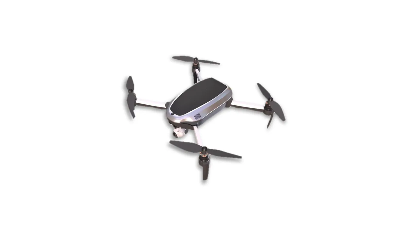
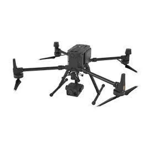
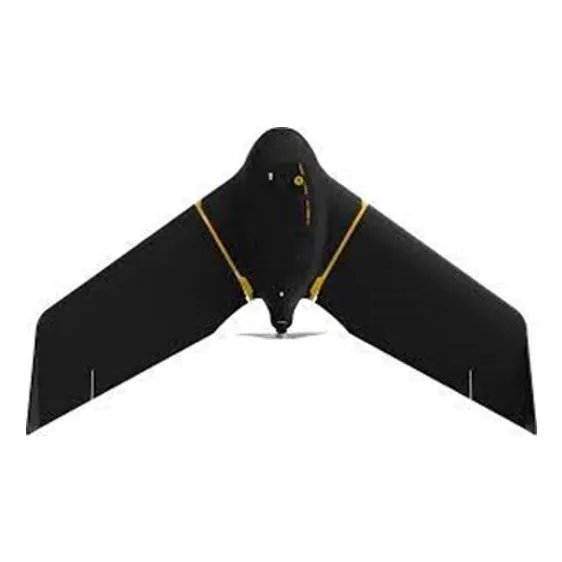
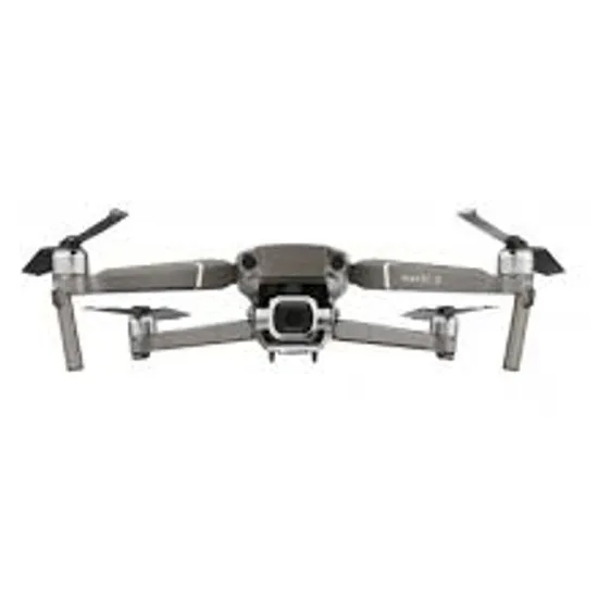
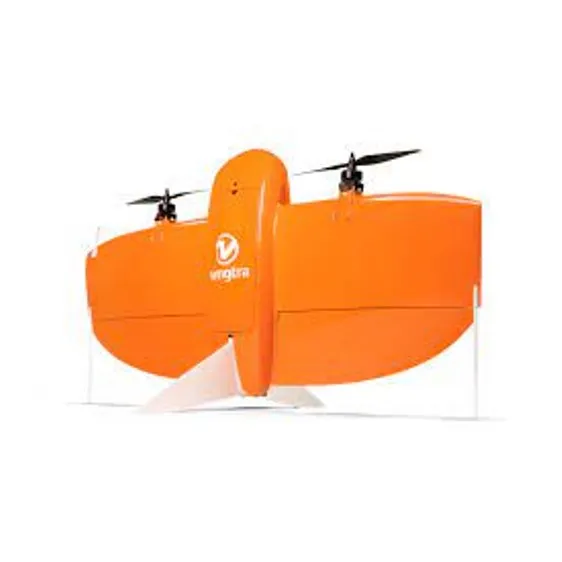
Before going through the steps, it is important to know that not every drone on the market is suitable for this kind of work. In fact, there are drones designed specifically for photogrammetry, such as the eBee X or the WingtraOne. In our case we used a DJI drone; within its wide range we find some recreational models such as the Mavic Pro 2 or even the Mavic Air 2, which can deliver very good results without reaching the quality of their bigger siblings.
Steps to follow
- 1.Flight planning with an app.
- 2.Carrying out the mission with the drone.
- 3.Processing the information with Agisoft Metashape.
Flight planning with an app
First, we need to define the area to cover so that we can take into account important factors such as how many batteries our drone will use while taking the photos, the height at which we will fly over the area, or the number and quality of the photos depending on the flight height. None of this has to be done on site: it can all be done remotely. Even so, it is advisable to have explored the area where we will fly beforehand, to avoid surprises such as possible obstructions (tall trees, antennas…) or new buildings that are not yet shown on the map.
For flight planning we used the app Copterus
There are many apps with very similar features, such as DroneDeploy and Pix4D Capture, among others.

Here, as mentioned above, we define the area our drone will map (E), setting a height (C) and other parameters such as the front and side overlap between images (at least 75% and 60% respectively), the flight path or the image format (F).
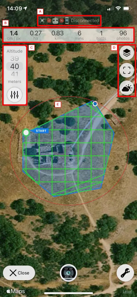
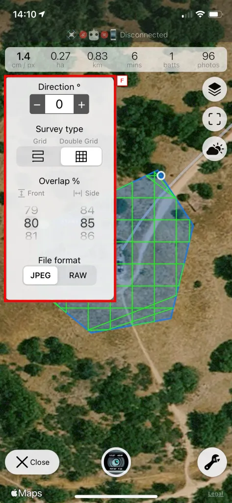
Flight planning. Setting the parameters in the Copterus app
It is important to know that when planning flights for orthomaps (mostly terrain), the flight path follows a grid, whereas for 3D buildings we need several alternative viewpoints, so a double-grid flight path is unavoidable. This matters because the mission our drone carries out through the app is flown with the camera pointing straight down at the ground (nadir view), leaving many blind spots uncovered.
Once the grid pass is complete, it should be supplemented with lower flights at different heights around our particular subject. We will cover this in more detail in the next section, when we fly the drone.
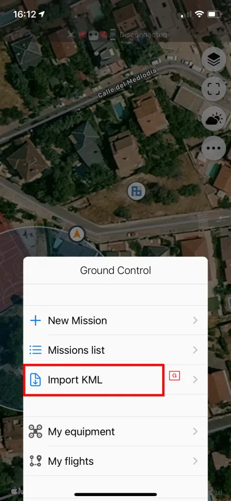
We can also import the points our drone will fly to from KML files
To round off this section: if we look at box (B) in the flight planning image, our mission will cover an area of 0.83m2, the flight will take an estimated 6 minutes, will use one battery at most and will take 96 photographs. Flying at an altitude of 40m, the images it produces will have a resolution of 1.4cm/pix. Changing the flight height or the area to cover will change these values.
It is also important to plan the time of day for the mission, since clouds can cast unwanted shadows on our 3D model (D), leaving underexposed and overexposed areas. That is why it is advisable to set the drone's camera to automatic exposure if we are unsure.
Carrying out the mission with the drone
This part is quick and simple. We just launch the mission from the app and the drone does the rest. It can be set to return to its starting point and land, or to hover at the last point waiting for a new command.
Which one we choose depends on our needs: for terrain, the nadir view may be enough to generate our point cloud. In our case, however, it was a ruined building, so we needed to take more photos from other angles.
This can be done manually or, depending on the drone's software, more automatically with preset flight modes such as Point of Interest, which flies circles at the height we want around a point we mark on the camera.
Depending on the volume to cover and the density we want in our point cloud, we will need more or fewer shots. Good practice is to fly three circular paths at different heights: 45º on the lowest path, 30º on the middle one and 10º on the highest. In any case, the sky must not appear in any of the shots, as this will lead to errors and false data in the processing software.
Once all the necessary photos have been taken, we can leave the site and start processing the information captured with the drone. Even so, if after processing we spot areas that have not been covered or have little information, we can go back to the mission site and add those passes to all the previous ones.
In the next post (3D scanning with drones II) we will explain how to process the data captured during the flight.